
An #ImageMagick recipe I use over an over is to remove the background of an image from two versions of the image: one with white background and another with dark background
magick light.png dark.png -alpha off ^( -clone 0,1 -compose difference -composite -separate -evaluate-sequence max -auto-level -negate ^) ^( -clone 0,2 -fx "v==0?0:u/v-u.p{0,0}/v+u.p{0,0}" ^) -delete 0,1 +swap -compose Copy_Opacity -composite no-background.png
I ❤️ ImageMagick 🙂
P.S. Recipe found at https://usage.imagemagick.org/masking/#two_background
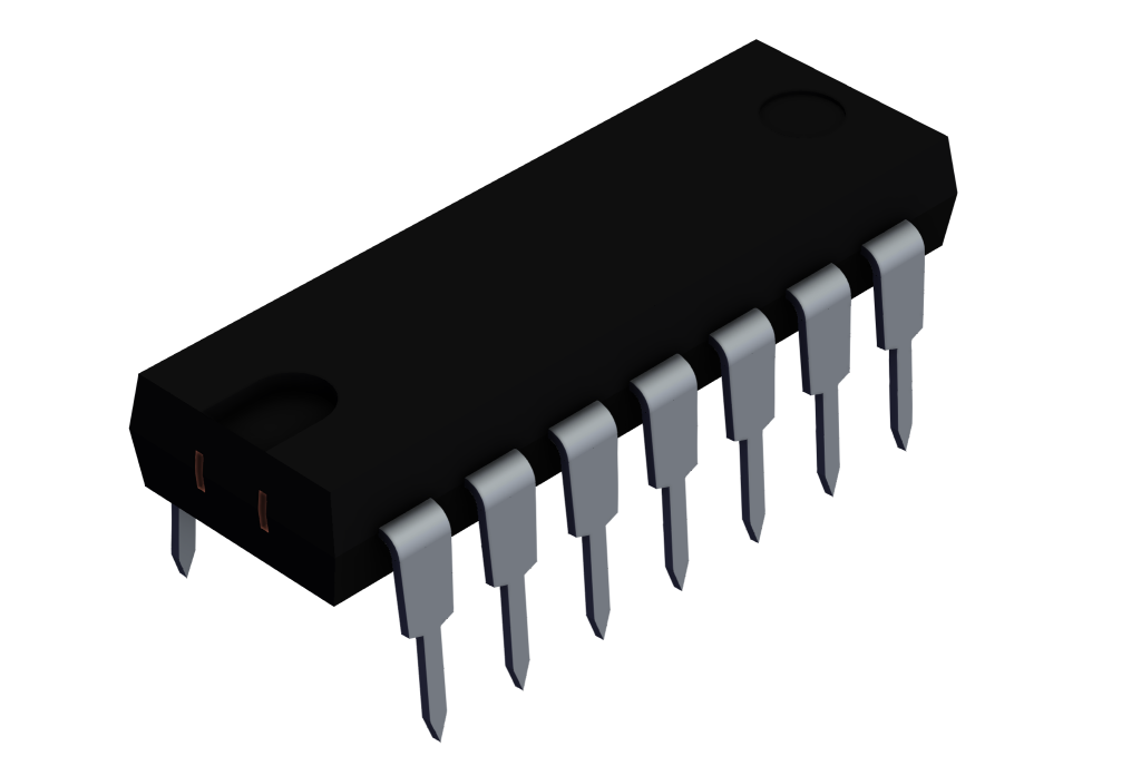
The image shows a 3D rendering of a black integrated circuit (IC) chip with 14 metallic pins—7 on each side. The rectangular chip has a notch on one end, used to indicate pin orientation. The metallic pins are bent downward for insertion into a circuit board. The background is plain white.
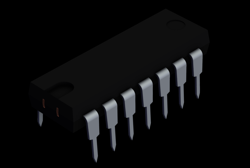
The image shows a 3D rendering of a black integrated circuit (IC) chip with 14 metallic pins—7 on each side. The rectangular chip has a notch on one end, used to indicate pin orientation. The metallic pins are bent downward for insertion into a circuit board. The background is plain black.

The image shows a 3D rendering of a black integrated circuit (IC) chip with 14 metallic pins—7 on each side. The rectangular chip has a notch on one end, used to indicate pin orientation. The metallic pins are bent downward for insertion into a circuit board. The background is transparent.
